Grid Cover Definition
A part in the grid structure must have a grid cover definition which specifies how the part interacts with the grid. In the most basic case, only the width and height values are needed. Each part in the same row or column must have the same size. The size does not have to exactly match the 3D mesh size. By default the part is added to the center of the cell, but an offset can be defined inside the GridOptionProperties. The cell size is larger than the mesh, there will be empty padding space around the mesh. On the other hand, if the cell is smaller, the mesh will partially overlap the neighboring cells.
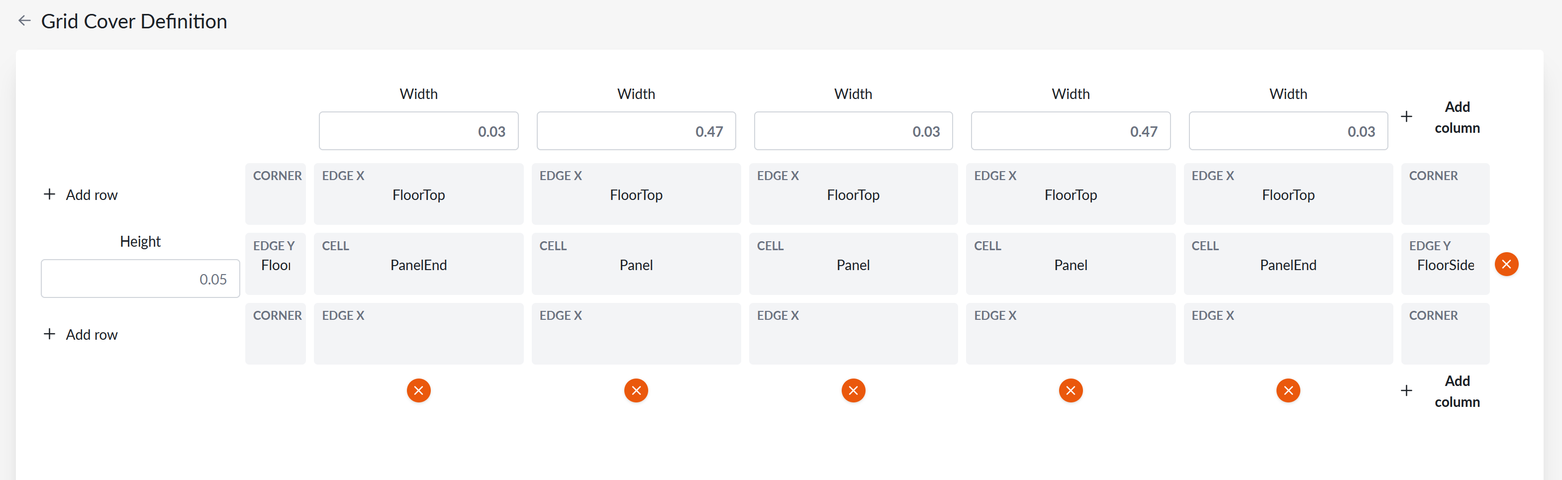
Multi-cell parts
It is possible to add additional rows and columns. This creates a multi-cell part, which occupies multiple cells in the grid. Each row and column can define its own size. The part is available only if all the sizes match the respective column and row sizes in the grid. If a new component is added partially or fully outside of the current grid bounds, a number of new rows and/or columns are added with sizes defined here.
If multiple rows and columns are used, the part geometry is added to the center of the combined area of all the cells, and can be offset in GridOptionProperties.
Area types and connectivity settings
In order to define connectivity rules in the grid, types must be added to grid parts. The types can be assigned separately to corners, edges, and cells. Area and corner types are used for overlap rules.
Edge types work in a slightly different way. When two parts are placed next to each other they share an edge. This is only allowed when the connection between the two edge types is configured so in the Grid Connectivity settings.
Rotated runtime variants
When GridOptionProperties.AllowedRotations is enabled, additional rotated variants of the same grid part are generated automatically during runtime data generation:
None: only authored orientation (0°)Symmetric: 0° and 180°Cardinals: 0°, 90°, 180°, and 270°
For generated variants, the following data is rotated consistently:
- Grid cover sizing and indexing (
SizesX,SizesY,CornerTypes,EdgeTypes,AreaTypes) - Connector-related values used for placement and 3D orientation (
ConnectionPointalignment, rotation, and static offset values)
In planner editing, in-place rotate is available only when the next rotation keeps the same row/column shape at that position. If rotating would change the occupied row/column shape, rotate is not offered for that placed component.